Hardware
This section includes an overview of the hardware components of Freddy 2.0
Hardware Components
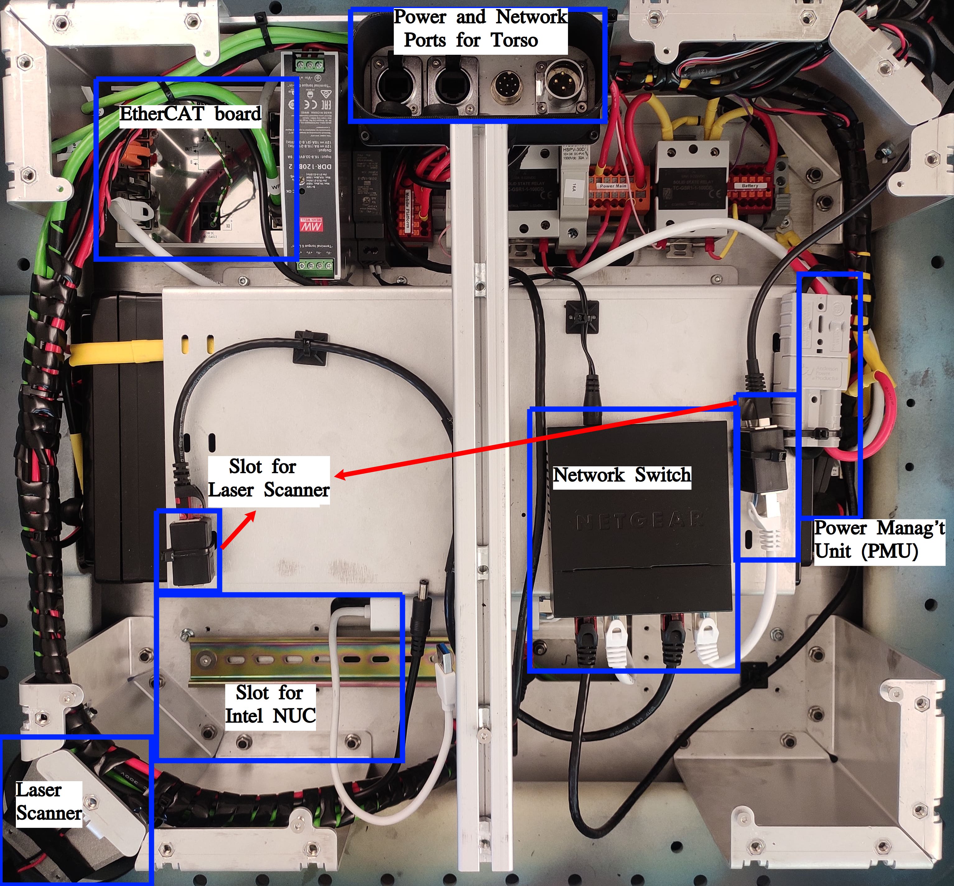
- Base of the robot is equipped with the following key components:
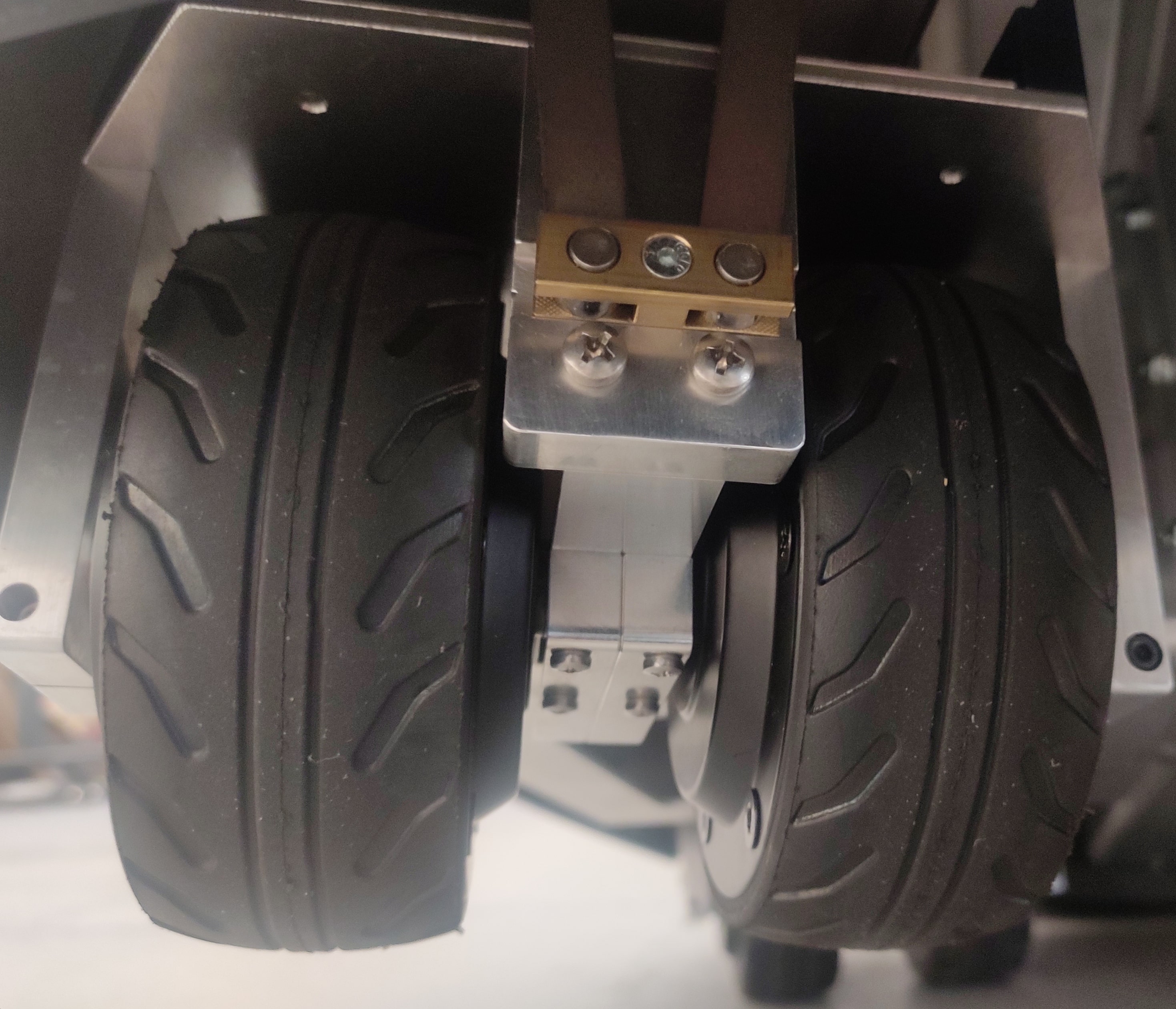
4 active wheel units, each with a pair of independently controlled wheels with hub motors
Laser scanner (Hokuyo UTM-10LX)
Power Management Unit (PMU), which is responsible for controlling the power supply to the wheels and the arms
EtherCAT board to which the wheels are connected
Intel NUC for processing
Network switch to allow communication with the rest of the components
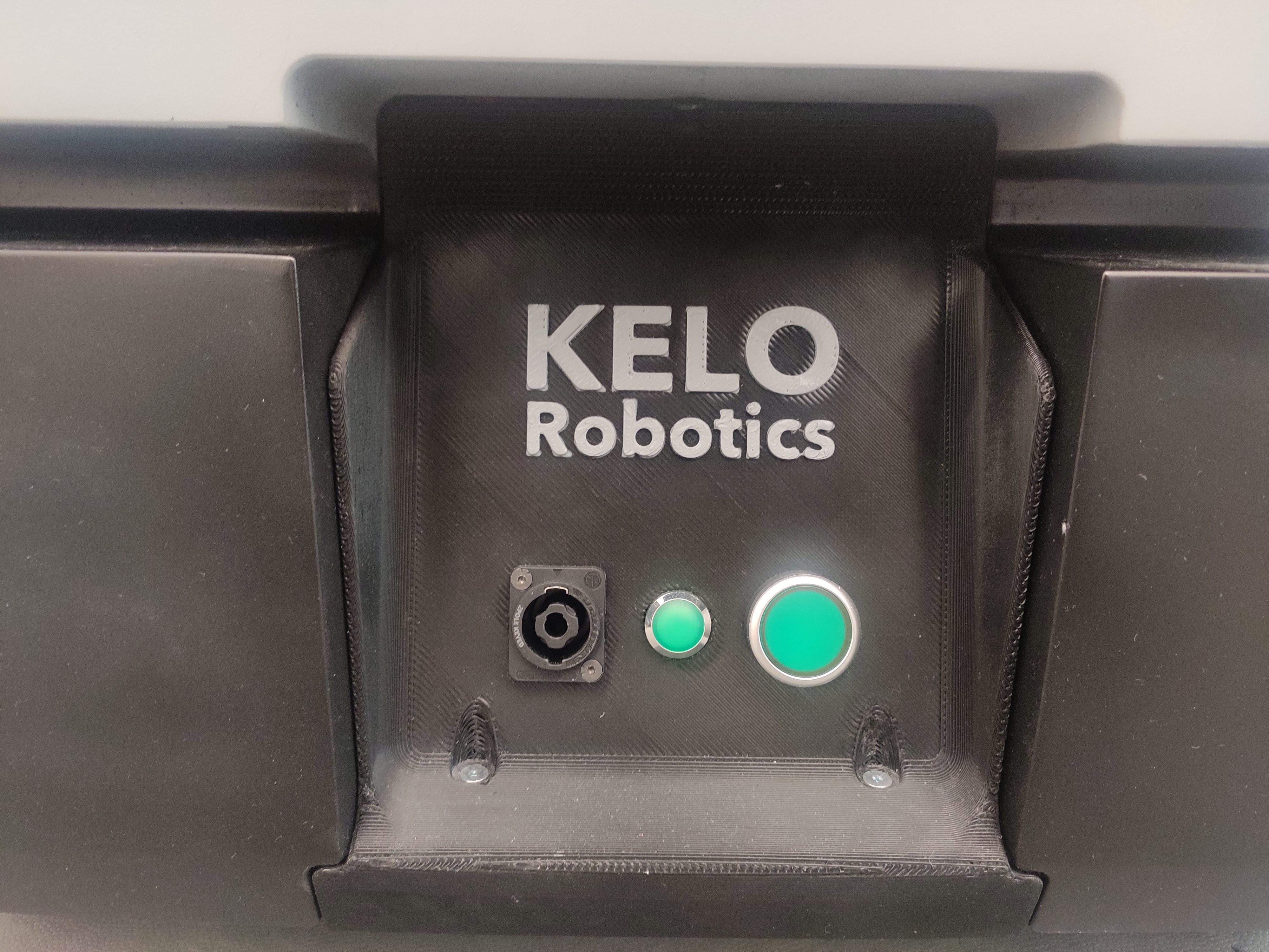
Power button and charging port
Ports for torso connection includes a power port, an ethernet port for communication, and an EtherCAT port for a wireless emergency stop device
Representation of the internal components of the base in top view
Representation of single wheel unit and the power button with charging port on the base of the robot
- Torso of the robot consists of the following components:
2 Kinova Gen3 arms
Ethernet switch enabling communication with both arms and the base
Ethernet port to access this switch
Power button and the emergency button
Antenna of wireless emergency stop device (RE5910) which is used to enable/disable the power supply to the base and the arms
Representation of the torso with ethernet port, power button, emergency button, and the antenna of the wireless emergency stop device

Communication Architecture
Individual wheels are connected to the EtherCAT board which his further connected to the switch at the base of the robot. Similarly, the ethernet cables from the individual arms are connected to a switch at the torso of the robot.
The power supply to the wheels and the arms are controlled by the PMU board.
Powering the Robot
Steps to Power On
Step1: Hold the power button on the base of the robot until the green LED turns on. Now the green LED light on the torso of the robot will start blinking and the red LED will turn on. This represents safe mode.
Step2: If not already done, pull the red coloured emergency button on the RE5910 and wait until the green LED on it to turn on. Now press the green button on the RE5910 and the same green LED will start blinking.
Step3: Now press the green button on the torso of the robot. The green LED on the torso will turn on and the red LED will turn off. This represents operational mode of the robot. Now the robot’s wheels will by default get the power and are available for communication. To enable power supply to the arms, a command needs to be sent to the PMU board. This is further discussed in the section describing the commands to control the power of the robot.
Steps to Power Off
Method1: Hold the power button the the base of the robot until it starts blinking and then release it.
Method2: Send the SHUTDOWN command to the PMU board. This is further discussed in the section describing the commands to control the power of the robot.
Charging the Robot
Connect the charger to the charging port on the robot’s base. The blinking green LED on the base of the robot indicates that the robot is charging. The robot can be charged while it is powered on or off.